
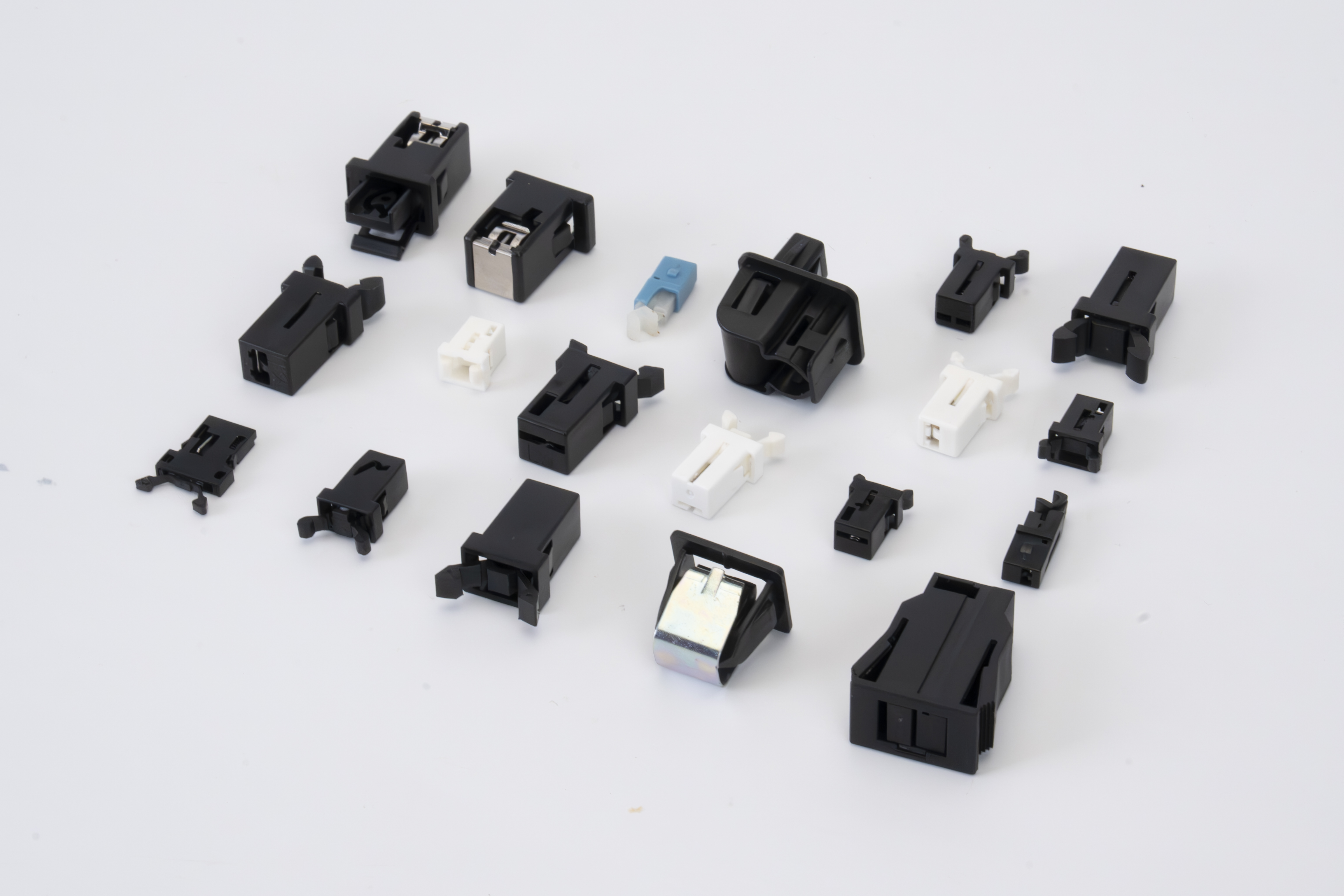
The door latch switch, also commonly known as the push-to-lock latch, has various names in the market. It typically refers to a structural latch that integrates both self-locking and spring-release functions.
Due to its simple installation method, convenient use, and compact structure, this type of latch is widely used in various lightweight door cover structures, such as the car eyeglass case application scenario in the video.
Different types of door latch switches vary in terms of external dimensions, but their working principles are essentially the same. This article will take one of the common types, the push-type door latch switch, as an example for illustration.
Structurally, the door latch switch primarily consists of four core components: the housing, the latch, the pull rod, and the spring. Inside the housing, there is a guide slot structure. The latch must be matched with the corresponding pull hook to ensure reliable locking of the door cover.
🌟The specific principle is as follows:
🌟Compression process:
🌟Tie Rod Trajectory ① Locking Process (Press to Lock) During the locking process, by pressing the pull hook, a downward force is indirectly applied to the buckle. The buckle then moves downward, with a stroke of approximately 5.8 mm, and simultaneously drives the tie rod to move along the trajectory shown in the diagram to position "1".
At this point, the pull rod starts to enter the guide slot structure of the housing. After releasing, under the action of the spring, the pull rod rebounds upward along the trajectory shown in the figure by about 1 mm, reaching position "2", and is stopped by the guide slot structure, thus achieving a locked state.
(During the process of moving the pull rod up by about 1 mm, the buckle and the pull hook will also move up by about 1 mm synchronously.) ② Ejection process (pressing again to unlock) During the ejection process, press the pull hook again, and the buckle will move downwards by about 1 mm, simultaneously driving the pull rod to move along the trajectory shown in the diagram to position "3".
At this point, the pull rod gradually escapes from the restriction of the guide slot. Upon releasing, the pull rod continues to move up along the trajectory shown in the diagram under the action of the spring, eventually reaching position "4" and fully returning to its initial position. The door cover then springs open, completing the unlocking and ejection process.
The process of the hook being locked (structural action description) involves the hook pressing downwards and pushing the buckle downwards as a whole. When the two sides of the buckle come into contact with the limiting structure inside the shell, the continued downward linear motion is restricted.
At this point, the buckle rotates inward, using its hinge as the axis of rotation, ultimately gripping and locking the pull hook, ensuring the reliable closure of the door cover. Key principle explanation: Why does the pull rod "automatically" enter the guide slot and move to the right, instead of reversing and returning to the left? Key principle explanation: Why does the pull rod "automatically" enter the guide slot and move to the right, instead of reversing and returning to the left?
The key to this structure lies in the design of the pull rod's rotating shaft. Unlike conventional circular rotating shafts, this rotating shaft adopts a semi-circular structure.
After the spring is compressed, the flat surface on the half-circle of the rotating shaft will align with the corresponding flat surface of the buckle, resulting in the pull rod not being completely vertical in the initial state but forming a certain angle with the vertical stroke. When the pull rod moves downwards and to the left along the inclined surface of the guide slot to the position shown in the figure, under the action of the spring's rebound force and due to the presence of the eccentric structure of the rotating shaft, the pull rod will naturally generate a moment of force that deflects it to the right, thus being guided into the guide slot and moving in the predetermined direction. Similarly, when the pull rod gradually escapes from the constraint of the guide slot, its force state changes, and under the action of the spring, a leftward deflection moment will be generated, prompting the pull rod to rotate until it returns to its initial position. Through the collaborative design of the asymmetric rotating shaft and guide slot structures, automatic switching of the pull rod's movement direction is achieved, allowing for locking and resetting without requiring additional control mechanisms.
📞 Welcome to inquire about technical issues and request sample support. We offer: ✅ 3D product images / structural diagrams ✅ Customization services ✅ Project selection guidance ✅ Overseas export support 📩 For further information, please call 400-996-1498 or send us a private message. Let's make product structures smarter, starting with this small lock latch!